Introduction
Impedance is a fundamental concept in electrical and electronic engineering that affects the performance of circuits. Understanding impedance is crucial for designing circuits, ensuring signal integrity, and optimizing power transfer. This blog explores the definition, units, formulas, and applications of impedance while providing comparisons and FAQs to enhance comprehension. We will also delve deeper into impedance matching, its importance in real-world applications, and how it influences various electronic components.
In an electrical circuit, impedance represents the extent to which electrical flow is opposed. It is important to know that because the impedance affects the output quality of the circuit and the device that comprises that circuit.
For example, consider audio devices like speakers. If a set of speakers has a higher impedance than the output impedance of the amplifier, the overall resistance is greater so the amplifier will not produce the maximum volume output. To produce this output, the resistance will have to be overcome, which will require more power.
Similarly, headphones with a low impedance will have a lower overall resistance and will therefore produce high-volume output. On the other hand, headphones with higher impedance will require a more powerful signal to produce the same volume output as the low-impedance headphones.
What is Impedance?
Here is a video that might help:
1. Impedance Definition in Electrical Terms
Impedance is the total opposition that an electrical circuit presents to the flow of alternating current (AC). It is a combination of resistance (R) and reactance (X) and is represented by the symbol Z.
In direct current (DC) circuits, only resistance matters, as reactance is zero. However, in AC circuits, reactance plays a crucial role, as capacitors and inductors introduce frequency-dependent opposition to current flow.
2. Impedance Unit
Impedance is measured in ohms (Ω), the same unit as resistance. However, unlike pure resistance, impedance can have both a real and an imaginary component due to the presence of reactance.
3. Impedance Formula
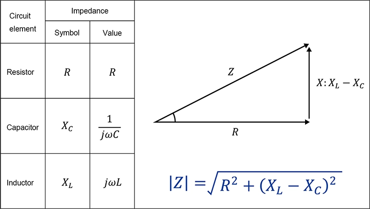
Impedance in an AC circuit is given by:
where:
• Z = impedance (ohms, Ω)
• R = resistance (ohms, Ω)
• X = reactance (ohms, Ω)
Reactance itself is frequency-dependent and varies based on the presence of inductors and capacitors.
Impedance vs Resistance: Key Differences
| Property | Impedance | Resistance |
|---|---|---|
| Definition | Total opposition to AC, including resistance and reactance | Opposition to current in both AC and DC circuits |
| Components | Resistance + Reactance | Only resistance |
| Frequency Dependence | Yes, depends on frequency | No, independent of frequency |
| Unit | Ohms (Ω) | Ohms (Ω) |
| Nature | Can be complex (real + imaginary parts) | Always real |
Resistance, denoted as R, is one of the components of impedance. Specifically, it is the real component of impedance. It is a measure of the extent to which a substance opposes the movement of electrons among its atoms, thus resulting in opposition to flowing current within an electrical circuit. The more easily the atoms give up and/or accept electrons, the lower the resistance, which is expressed as a positive real number and expressed in ohms.
Materials with low resistance are known as electrical conductors. As the term suggests, they are good conductors of electricity. Examples include the following:
• Copper.
• Silver.
• Gold.
• Aluminum.
High-resistance substances are poor conductors of electricity and are called insulators or dielectrics. Common insulators include the following:
• Polyethylene.
• Mica.
• Glass.
• Porcelain.
• Rubber.
• Plastic.
Materials with intermediate levels of resistance are classified as semiconductors. Silicon is one of the best-known semiconductors; here are a few others:
• Germanium.
• Gallium arsenide.
• Gallium nitride.
• Indium phosphide.
• Graphene.
• Pyrite.
The phenomenon of resistance is observed with both alternating current (AC) and direct current (DC). That said, impedance is a more useful way to measure the resistance to electrons moving through a substance for AC signals, which tend to be more complex than DC signals, and to measure resistance at specific frequencies. It's also important to note that the resistance and impedance are the same for DC signals.
The basic formula for impedance and resistance is the same: R = V/I and Z = V/I, where V = voltage (volts) and I = current (amperes).
The unit of measurement for both is ohms. However, resistance does not vary by frequency changes. Adding reactance to the impedance formula produces a more advanced formula that takes into account frequency information due to the contributions of capacitance and inductance, which are frequency-dependent. The ability to do so is very useful for certain applications, including audio applications such as audio speakers whose output is affected by their impedance values.
Impedance in Different Components
1. Impedance of Resistor
For a pure resistor, impedance is equal to its resistance:
Since a resistor does not have reactance, its impedance does not change with frequency.
2. Impedance of Capacitor
For a capacitor, the impedance depends on frequency:
where:
• C = capacitance (farads, F)
• f = frequency (hertz, Hz)
• j = imaginary unit
• ω = angular frequency (rad/s)
As frequency increases, the impedance of a capacitor decreases. This property is widely used in filtering applications and reactive power compensation.
3. Impedance of Inductor
For an inductor, the impedance is:
where:
• L = inductance (henrys, H)
• f = frequency (hertz, Hz)
As frequency increases, the impedance of an inductor increases. Inductors are commonly used in RF applications and power electronics for energy storage and filtering.
What is Impedance Matching?
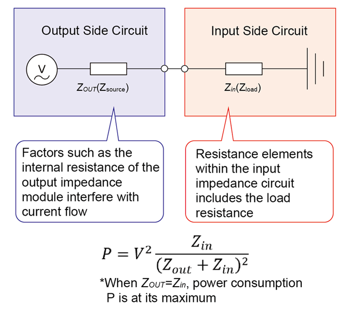
Impedance matching is the process of ensuring that the impedance of a source matches the impedance of its load to maximize power transfer and minimize signal reflection. This is especially important in RF circuits, audio systems, and transmission lines.
1. Impedance Matching Formula
For maximum power transfer:
where:
• Z_source = source impedance
• Z_load = load impedance
2. Impedance Matching Methods
There are several ways to achieve impedance matching:
• Resistive Matching: Using resistors to balance the impedance.
• Transformers: Step-up or step-down transformers adjust impedance ratios.
• LC Networks: Combinations of inductors and capacitors are used in high-frequency applications.
• Quarter-Wave Transformers: Used in RF transmission lines to match impedances.
• Stub Matching: Open or short-circuited transmission line segments create impedance compensation.
3. Impedance Matching Calculator
To simplify calculations, an impedance matching calculator can be used. These tools help determine the correct values of resistors, capacitors, or inductors needed for impedance matching.
Calculating impedance in series circuits
In a series RLC circuit, resistances and reactances add together independently (R = Resistor, L = Inductor and C = Capacitor).
Example 1. A resistance of 100 ohms is connected in a series circuit that includes an inductor. The circuit frequency is 4 MHz. The inductance, measured in Henries (H) is 10 H. Considering these values, here's how the complex impedance of the circuit will be calculated:
ZRL = R + jXL = 100.00 ohms + j251.33 ohms
Example 2. Now suppose the circuit includes a capacitor with a capacitance of 0.0010000 Farads (F) instead of the inductor. The resistance is still 100 ohms. The resulting complex impedance at 4 MHz will now be calculated as:
ZRC = R - jXC = 100.00 ohms - j39.789 ohms
Example 3. If all three components are connected in series, then the reactances add, yielding a complex impedance of:
ZRLC = 100 + j251.33 - j39.789 = 100 ohms + j211.5 ohms
This is the equivalent of a 100-ohm resistor in series with an inductor having +j211.5 ohms of reactance.
At 4.0000 MHz, this reactance is presented by an inductance of 8.415 H, as determined by plugging the numbers into the formula for inductive reactance and working backward.
Calculating impedance in parallel circuits
Compared to series RLC circuits, parallel RLC circuits are more complicated to analyze, making it harder to calculate the complex inductance.
To calculate the effects of capacitive and inductive reactance in parallel, the quantities are converted to inductive susceptance and capacitive susceptance, where susceptance is the reciprocal of reactance. Susceptance combines with conductance, which is the reciprocal of resistance, to form complex admittance, which is the reciprocal of complex impedance.
What is Impedance in a Circuit?
In practical circuits, impedance affects voltage, current flow, and power transfer. Understanding impedance is essential for designing filters, amplifiers, antennas, and high-speed digital circuits. Many signal integrity issues, such as reflections and losses in transmission lines, stem from impedance mismatches. Of course, these are overly simplistic and short explanations of complex concepts. For a deeper understanding of these concepts and how they affect the performance of electrical systems in the real world, further study is recommended using an intermediate electronics text or reference book.
Applications of Impedance
• RF and Microwave Circuits: Ensuring proper impedance matching for efficient power transfer.
• Audio Systems: Matching speaker impedance with amplifiers to avoid signal loss.
• Power Systems: Managing reactive power for efficient energy distribution.
• Medical Electronics: Designing impedance-sensitive biomedical sensors.
• High-Speed Digital Systems: Maintaining signal integrity in printed circuit boards (PCBs).
FAQ on Impedance
1. What is Impedance in Electricity?
Impedance in electricity refers to the total opposition a circuit offers to AC current, considering both resistance and reactance.
2. What is Impedance Matching?
Impedance matching is the technique of making source and load impedances equal to achieve optimal power transfer.
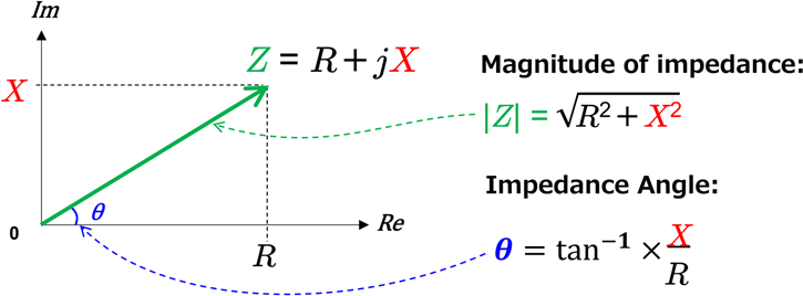
3. How Do You Calculate Impedance?
Use the formula: where X is the reactance.
4. Why is Impedance Important?
Impedance influences circuit performance, power transfer efficiency, and signal integrity in electrical and electronic systems.
5. Does DC Have Impedance?
In DC circuits, impedance equals resistance since reactance (which depends on frequency) is zero.
6. How Does Frequency Affect Impedance?
• Capacitors: Impedance decreases with increasing frequency.
• Inductors: Impedance increases with increasing frequency.
• Resistors: Impedance remains constant.
7. What Happens if Impedance is Not Matched?
Mismatched impedance can lead to power loss, signal reflections, voltage standing wave ratio (VSWR) issues, and inefficient circuit performance.
Conclusion
Understanding impedance is crucial for engineers, designers, and electronics enthusiasts. Whether you're dealing with resistors, capacitors, inductors, or designing circuits with impedance matching requirements, mastering impedance ensures better circuit performance and efficiency. By using formulas, calculators, and practical knowledge, you can optimize your electrical designs effectively. Impedance plays a critical role in multiple applications, from audio and RF systems to power distribution and biomedical electronics, making it an essential concept for anyone working with electrical circuits.
Written by Icey Ye from AIChipLink.
AIChipLink, one of the fastest-growing global independent electronic component distributors in the world, offers millions of products from thousands of manufacturers. Whether you need assistance finding the right part or electronic components manufacturers for your design, you can contact us via phone, chat or e-mail. Our support team will answer your inquiries within 24 hours.


